Understanding the fuse box diagram of your 2008 Mercedes C300 is crucial for diagnosing and resolving electrical issues. This guide provides a detailed overview of the fuse box locations and fuse assignments for your Mercedes-Benz C-Class W204 model, produced between 2007 and 2014, specifically focusing on the 2008 C300. Whether you’re dealing with a blown fuse or performing routine maintenance, this information will help you navigate your vehicle’s electrical system with confidence.
Instrument Panel Fuse Box
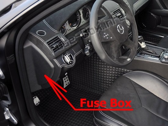
Fuse Box Location
The instrument panel fuse box in your Mercedes-Benz C300 is conveniently located on the driver’s side, concealed behind a protective cover. Accessing this fuse box is straightforward, allowing for quick checks and fuse replacements when needed.
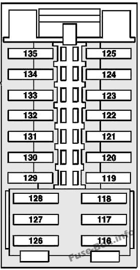
Fuse Box Diagram
The diagram below illustrates the fuse layout for the instrument panel fuse box in your 2008-2014 Mercedes-Benz C-Class. Refer to this diagram in conjunction with the fuse assignment table to accurately identify and manage the fuses related to various components within your vehicle’s interior.
Fuse Assignments – Instrument Panel Fuse Box
| Fuse Number | Fused Function | Ampere (Amp) |
|---|---|---|
| 116 | Driver seat control unit | 30 |
| 117 | Adaptive damping system control unit | 15 |
| 118 | Spare | – |
| 119 | Rear blower motor / AMG Performance Media control unit (valid as of 06/01/12) | 7.5 |
| 120 | Spare | – |
| 121 | Spare | – |
| 122 | Spare | – |
| 123 | Steering column tube module control unit | 10 |
| 124 | Spare | – |
| 125 | Spare | – |
| 126 | Front passenger seat control unit | 30 |
| 127 | Spare | – |
| 128 | Spare | – |
| 129 | Valid for engine 156: Oil cooler fan motor relay | 20 |
| 130 | Spare | – |
| 131 | Spare | – |
| 132 | Spare | – |
| 133 | Spare | – |
| 134 | Spare | – |
| 135 | Spare | – |
Engine Compartment Fuse Box
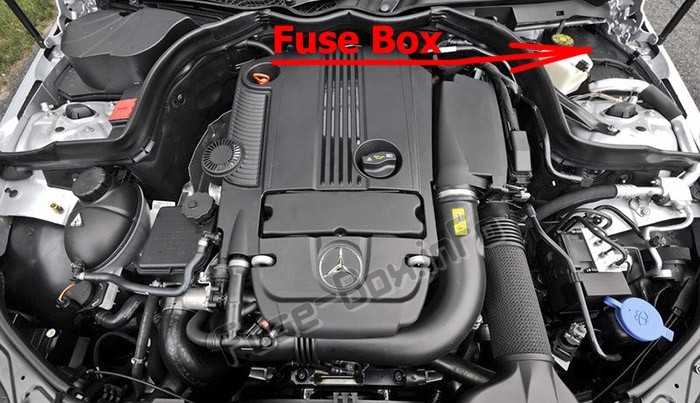
Fuse Box Location
For components under the hood, the engine compartment fuse box in your Mercedes-Benz C300 W204 is situated on the left-hand side of the engine bay. It is protected by a cover, ensuring the fuses remain shielded from engine heat and debris.
Fuse Box Diagram
The engine compartment fuse box diagram, along with the corresponding table, details the fuses and relays that control essential engine and vehicle functions. Understanding this layout is vital for troubleshooting issues related to your 2008 Mercedes C300’s performance.
Fuse and Relay Assignments – Engine Compartment Fuse Box
| Fuse/Relay Number | Fused Function | Ampere (Amp) |
|---|---|---|
| 1 | Electronic Stability Program control unit | 25 |
| 2 | Left front door control unit | 30 |
| 3 | Valid up to 03/31/10: Right front door control unit / Valid as of 04/01/10 with model 204.0/2/9: Right rear door control unit | 30 |
| 4 | Up to 08/31/08: Fuel pump control unit / Valid for engine 156 up to 08/31/08: Left fuel pump control unit, Right fuel pump control unit / Valid for engine 642, engine 651: Fuel filter condensation sensor with heating element / Valid for engine 651 up to 05/31/10, engine 646: Control unit for fuel filter condensation sensor with heating element | 7.5 |
| 4 | Valid for diesel engine as of 09/01/08: Fuel filter condensation sensor with heating element / Valid for engine 276 (USA, South Korea): Activated charcoal canister shutoff valve / Valid for model 204.0/2/3 as of 03/01/11, 204.9 as of 06/01/12: Headlamp control unit | 20 |
| 5 | Rear SAM control unit with fuse and relay module / Valid as of 06/01/10 Exterior lights switch / Valid for engine 156 Black Series as of 07/01/11: Rear axle differential coolant circuit relay | 7.5 |
| 6 | Valid for diesel engine: ME-SFI [ME] control unit / Valid for gasoline engine: CDI control unit | 10 |
| 7 | Starter | 20 |
| 8 | Supplemental restraint system control unit | 7.5 |
| 9 | Glove compartment power outlet | 15 |
| 10 | Wiper motor | 30 |
| 11 | Audio/COMAND display / Audio/COMAND control panel / Holder for navigation module | 7.5 |
| 12 | Automatic air conditioning control and operating unit / Upper control panel control unit | 7.5 |
| 13 | Steering column module control unit / Multifunction camera | 7.5 |
| 14 | Electronic Stability Program control unit | 7.5 |
| 14 | Headlamp control unit | 20 |
| 15 | Supplemental restraint system control unit | 7.5 |
| 16 | Diagnostic connector (up to 05/31/09) / Mobile phone electrical connector / Valid for transmission 722: Electronic selector lever module control unit | 5 |
| 16 | ECO start/stop function: Electric transmission oil pump | 20 |
| 17 | Panoramic sliding roof control module / Overhead control panel control unit | 30 |
| 18 | Valid up to 11/30/09: Exterior lights switch / Valid for model 204.0/2 as of 03/01/11, model 204.3: Upper control panel control unit / Valid for model 204.0/2 up to 02/28/11, model 204.9: Instrument panel climate control LIN positive line connector sleeve / Vehicle interior and harness for taillamp electrical connector | 7.5 |
| 19 | Electric steering lock control unit / Electronic ignition lock control unit | 20 |
| 20 | Electronic Stability Program control unit | 40 |
| 21 | Stop lamp switch / Glove compartment lamp switch / Front passenger seat occupied recognition and ACSR / Electronic Toll Collection preinstallation electrical fuse (Japan) | 7.5 |
| 22 | Combustion engine fan motor and air conditioning with integrated control / Electrical connector for interior harness and engine wiring harness | 15 |
| 23 | Electrical connector for interior harness and engine wiring harness / Valid for diesel engine: Rear SAM control unit with fuse and relay module CDI control unit Terminal 87 connector sleeve / Valid for engine 271: Terminal 87 M1e connector sleeve / Valid for engine 272: Circuit 87 M1i connector sleeve | 20 |
| 24 | Electrical connector for interior harness and engine wiring harness / Interior and engine wiring harness electrical connector / Valid for engine 642: Radiator shutters actuator / Valid for engine 272: Terminal 87 M1e connector sleeve / Valid for diesel engine: Terminal 87 connector sleeve / Valid for engine 646: CDI control unit | 15 |
| 25 | Valid for engine 156, 271, 272, 274, 276: ME-SFI [ME] control unit / Valid for diesel engine: Oxygen sensor upstream of catalytic converter / Valid as of 06/01/10 for model 204.3 with engine 651 Sport Edition: Exhaust system sound generator control unit | 15 |
| 26 | Radio / Radio with auto pilot system / COMAND controller unit | 20 |
| 27 | Electric steering lock control unit / Electronic ignition lock control unit / Valid for diesel engine: CDI control unit / Valid for gasoline engine: ME-SFI [ME] control unit | 7.5 |
| 28 | Instrument cluster | 7.5 |
| 29 | Right front lamp unit | 10 |
| 30 | Left front lamp unit / Valid for engine 642: Electrical connector for interior harness and engine wiring harness | 10 |
| 31A | Left fanfare horn / Right fanfare horn | 15 |
| 31B | Left fanfare horn / Right fanfare horn | 15 |
| 32 | Valid for engine 156, 271, 272, 276: Electric air pump | 40 |
| 32 | Valid for engine 156: Oil cooler fan motor | 20 |
| 33 | Valid for transmission 722.6: Electronic transmission-control control unit / Valid for transmission 722.9: Fully integrated transmission control controller unit | 10 |
| 34 | Valid for engine 271, 272 as of 09/01/08: Fuel pump control unit / Valid for engine 156 as of 09/01/08: Left fuel pump control unit, Right fuel pump control unit | 7.5 |
| 35 | Valid as of 03/01/11: Electronic Stability Program control unit | 5 |
| 36 | Valid as of 03/01/11: DISTRONIC electric controller unit / Valid for model 204.902/982/984: Electrohydraulic power steering | 7.5 |
| Relay | ||
| J | Circuit 15 relay | |
| K | Terminal 15R relay | |
| L | Backup relay | |
| M | Circuit 50 starter relay | |
| O | Engine circuit 87 relay / Fanfare horn relay | |
| P | Valid for engine 156, 272, 276: Secondary air injection relay | |
| Q | Backup relay | |
| R | Chassis circuit 87 relay |
Front Pre-fuse Box (up to 2010)
For earlier models of the 2008 Mercedes C300, specifically up to 2010, the front pre-fuse box in the engine compartment has a specific configuration. This pre-fuse box handles high-current fuses that protect major electrical systems.
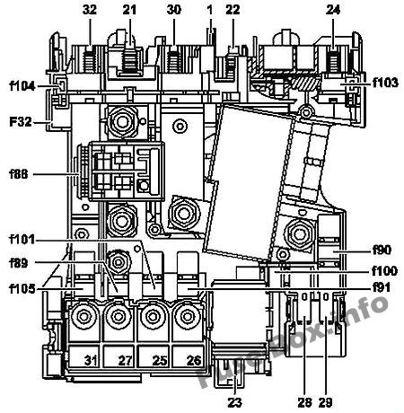
Fuse Assignments – Front Pre-fuse Box (up to 2010)
| Fuse Number | Fused Function | Ampere (Amp) |
|---|---|---|
| 88 | Pyrofuse: Alternator, Starter | – |
| 89 | Front SAM control unit with fuse and relay module | 125 |
| 90 | Rear SAM control unit with fuse and relay module | 40 |
| 91 | Combustion engine fan motor and air conditioning control | 80 |
| 100 | Air conditioner housing | 40 |
| 101 | Valid for gasoline engine: Front SAM control unit | 60 |
| 103 | Valid for diesel engine: PTC heater booster | 150 |
| 104 | Interior fuse box | 70 |
| 105 | Front SAM control unit with fuse and relay module | 100 |
| 106 | Rear SAM control unit with fuse and relay module | 150 |
| 107 | Spare | – |
| 108 | Spare | – |
| 109 | Spare | – |
| 110 | Spare | – |
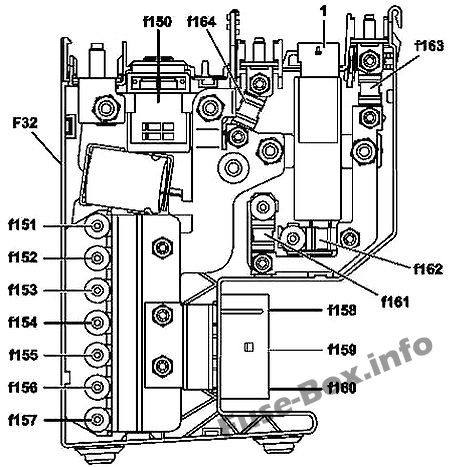
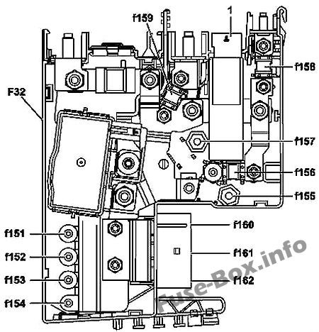
Front Pre-fuse Box (as of 2010)
For 2008 Mercedes C300 models manufactured from 2010 onwards, the front pre-fuse box configuration may differ, especially with or without the ECO start/stop function. Ensure you identify the correct diagram for your vehicle’s specifications.
Front Pre-fuse Box (as of 2010) – without ECO start/stop
Front Pre-fuse Box (as of 2010) – with ECO start/stop
Fuse Assignments – Front Pre-fuse Box (as of 2010)
| Fuse Number | Fused Function | Ampere (Amp) |
|---|---|---|
| 150 | Without ECO start/stop: Pyrofuse 88 / ECO start/stop: Alternator, Starter | 400 / 200 |
| 151 | Combustion engine fan motor and air conditioning with integrated control | 100 |
| 152 | Front SAM control unit with fuse and relay module | 150 |
| 153 | Without ECO start/stop: Spare / ECO start/stop function and front battery position: Front SAM control unit with fuse and relay module | 100 / 60 |
| 154 | ECO start/stop function and front battery position: Front SAM control unit with fuse and relay module / Valid for diesel engine and ECO start/stop: PTC heater booster | 60 / 150 |
| 155 | Without ECO start/stop: Spare / ECO start/stop function: Spare | 50 / 100 |
| 156 | Valid for diesel engine without ECO start/stop: PTC heater booster / ECO start/stop function: Front SAM control unit with fuse and relay module | 150 / 100 |
| 157 | Valid for model 204.902/982/984 without ECO start/stop function: Electrohydraulic power steering / ECO start/stop: Spare | 100 / – |
| 158 | Without ECO start/stop: Blower regulator / ECO start/stop: Rear SAM control unit with fuse and relay module | 50 / 150 |
| 159 | Special-purpose vehicle multifunction control unit / ECO start/stop: Additional battery relay | 50 / 200 |
| 160 | Without ECO start/stop: Spare / ECO start/stop: Blower regulator | 60 / 50 |
| 161 | Without ECO start/stop: Front SAM control unit with fuse and relay module / Special-purpose vehicle multifunction control unit | 100 / 50 |
| 162 | Without ECO start/stop: Spare / ECO start/stop: Spare | 100 / 60 |
| 163 | Without ECO start/stop: Rear SAM control unit with fuse and relay module | 150 |
| 164 | Without ECO start/stop function: Rear SAM control unit with fuse and relay module | 80 |
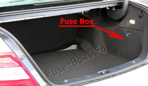
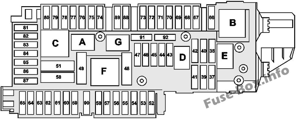
Luggage Compartment Fuse Box
Fuse Box Location
The luggage compartment fuse box in your Mercedes-Benz C300 is situated in the trunk, on the right-hand side. It is located behind a trim panel, ensuring it is protected yet accessible for maintenance.
Fuse Box Diagram
The luggage compartment fuse box is critical for the electrical functions at the rear of your vehicle. There are two versions of the diagram available, ensure you identify the correct version that matches your 2008 Mercedes C300 for accurate fuse management.
Luggage Compartment Fuse Box Diagram – Version 1
Luggage Compartment Fuse Box Diagram – Version 2
Fuse and Relay Assignments – Luggage Compartment Fuse Box
| Fuse/Relay Number | Fused Function | Ampere (Amp) |
|---|---|---|
| 37 | As of 2008: Driver seat NECK-PRO head restraint solenoid, Front passenger seat NECK-PRO head restraint solenoid / Up to 2008: Driver seat NECK-PRO head restraint solenoid, Front passenger seat NECK-PRO head restraint solenoid | 5 / 7.5 |
| 38 | Tailgate wiper motor | 15 |
| 39 | Valid for model 204.0/2/9 except vehicles for Great Britain up to 05/31/09: Left rear door control unit | 30 |
| 40 | Spare | – |
| 41 | Valid for model 204.0/2/9 up to 03/31/10: Right rear door control unit / Valid as of 04/01/10 Right front door control unit | 30 |
| 42 | Valid for gasoline engine or engine 642 as of 12/01/09 or engine 651 as of 06/01/09: Fuel pump control unit / Valid for engine 646 or engine 642 up to 11/30/09 or engine 651 up to 05/31/09: Fuel pump / Valid for gasoline engine (up to 2009): Fuel pump control unit | 25 / 20 |
| 43 | Valid as of 06/01/09 with automatic air conditioning: Rear blower motor | 5 |
| 44 | Switch group, right front seat setting / Front passenger seat partially electric seat adjustment switch | 30 |
| 45 | Left front seat adjustment switch group / Driver seat partially electric seat adjustment switch | 30 |
| 46 | Antenna amplifier for rear window FM antenna / Alarm siren / Interior protection and tow-away protection control unit / Rear window antenna amplifier 1 / TV 1 antenna amplifier and DAB Band III / DAB band III antenna / TV 2 antenna amplifier and KEYLESS-GO / KEYLESS-GO antenna amplifier | 7.5 |
| 47 | Spare | – |
| 48 | Spare | – |
| 49 | Rear window heater | 40 |
| 50 | Right front reversible emergency tensioning retractor | 50 |
| 51 | Left front reversible emergency tensioning retractor (A76) | 50 |
| 52 | Spare | – |
| 53 | As of 2008: Trailer recognition control unit / Up to 2008: Trailer recognition control unit | 15 / 30 |
| 54 | Up to 05/31/09: Trailer recognition control unit / Valid for model 204.075/077/275/277: Driver seat lumbar support and side bolster adjustment switch group, Front passenger seat lumbar support and side bolster adjustment switch group, Front passenger seat AMG valve block, Driver seat AMG valve block / As of 06/01/09: Trailer recognition control unit | 7.5 / 15 |
| 55 | Valid as of 06/01/09: AdBlue | 5 |
| 56 | Trailer recognition control unit / Trailer socket / Valid for model 204.077/277/377 up to 05/31/09: Driver seat lumbar support and side bolster adjustment switch group, Front passenger seat lumbar support and side bolster adjustment switch group, Front passenger seat AMG valve block, Driver’s seat AMG valve block | 15 / 5 |
| 57 | Trailer recognition control unit | 20 |
| 58 | As of 2008: Trailer recognition control unit / Up to 2008: Trailer recognition control unit | 20 / 30 |
| 59 | As of 2008: Parking system control unit, Left front bumper DISTRONIC (DTR) sensor, Right front bumper DISTRONIC (DTR) sensor, Intelligent radar sensor for left rear bumper, Intelligent radar sensor for right rear bumper / Up to 2008: PARKTRONIC control unit, Radar sensors control unit | 5 / 7.5 |
| 60 | Multicontour seat pneumatic pump | 7.5 |
| 61 | Liftgate-control control unit | 40 |
| 62 | Driver seat control unit | 30 |
| 63 | Front passenger seat control unit | 30 |
| 64 | DC/AC converter control unit | 25 |
| 65 | Adaptive damping system control unit / Steering column tube module control unit | 15 |
| 66 | Spare | – |
| 67 | As of 2008: Sound system amplifier control unit / Up to 2008: Sound system amplifier control unit | 30 / 40 |
| 68 | Spare | – |
| 69 | Rear bass speaker amplifier | 20 |
| 70 | Tire pressure monitor control unit | 5 |
| 71 | Front cigarette lighter with ashtray illumination / Front vehicle interior power outlet | 15 |
| 72 | Cargo area connector box 115 V power outlet | 15 |
| 73 | Diagnostic connector (as of 06/01/09) / Stationary heater radio remote control receiver / Valid for engine 156 as of 07/01/11: Transmission mode control unit | 7.5 |
| 74 | KEYLESS-GO control unit | 15 |
| 75 | Stationary heater unit | 20 |
| 76 | Vehicle interior power outlet | 15 |
| 77 | Weight Sensing System (WSS) control unit | 7.5 |
| 78 | Left front seat ventilation blower regulator / Right front seat ventilation blower regulator | 7.5 |
| 79 | Parking system control unit | 5 |
| 80 | Video and radar sensor system control unit / Parking system control unit | 7.5 |
| 81 | Media interface control unit | 5 |
| 82 | Cellular telephone system compensator UMTS / TV tuner control unit (up to 05/31/09; Japan) / Digital TV tuner (up to 05/31/09; Japan) | 5 |
| 83 | Electronic Toll Collection control unit (Japan) / Emergency call system control unit / Reversing camera / Left rear display / Right rear display | 7.5 |
| 84 | Satellite digital audio radio (SDAR) control unit / SDAR/high definition tuner control unit / Digital Audio Broadcasting control unit / Backup camera power supply module / Backup camera control unit / 360° camera control unit | 7.5 |
| 85 | TV tuner control unit (up to 05/31/09; Japan) / Digital TV tuner (as of 06/01/09; Japan) | 7.5 |
| 86 | DVD player | 7.5 |
| 87 | Emergency call system control unit | 7.5 |
| 88 | Valid as of 06/01/09 Spare | – |
| 89 | Valid as of 06/01/09: Trailer recognition control unit / Valid as of 06/01/09 with engine 156: Oil cooler fan motor relay | 20 |
| 90 | Valid as of 06/01/09 AdBlue® fuse block, AdBlue supply relay | 40 |
| 91 | DC/AC converter control unit / ECO start/stop: Transmission oil auxiliary pump control unit / Valid for engine 642: Vent line heater element | 25 / 20 |
| 92 | Valid as of 06/01/09 Spare | – |
| Relay | ||
| A | Terminal 15 relay | |
| B | Circuit 15R relay (1) | |
| C | Heated rear window relay | |
| D | Valid for diesel engine: Fuel pump relay | |
| E | Tailgate windshield wiper relay | |
| F | Seat adjustment relay | |
| G | Circuit 15R relay (2) |
Rear Pre-fuse Box
Located near the luggage compartment fuse box, the rear pre-fuse box contains high-amp fuses that supply power to major systems in the rear of your 2008 Mercedes C300.
Fuse Assignments – Rear Pre-fuse Box
| Fuse Number | Fused Function | Ampere (Amp) |
|---|---|---|
| 111 | Valid for gasoline engine: ME-SFI [ME] control unit / Valid for diesel engine: CDI control unit | 60 |
| 112 | Special-purpose vehicle multifunction control unit | 80 |
| 113 | Valid for engine 156: Left fuel pump control unit, Right fuel pump control unit | 40 |
| 114 | Spare | – |
| 115 | Special-purpose vehicle multifunction control unit | 100 |
By utilizing these fuse box diagrams and assignment tables, you can effectively diagnose and resolve electrical problems in your 2008 Mercedes C300, ensuring your vehicle remains in top operating condition. Remember to always consult your vehicle’s manual for the most accurate and up-to-date information.
For further assistance and information, explore these helpful resources:
How to check the fuses in your car
Step-by-step guide to replace a blown fuse
Understanding why car fuses blow frequently
Learn about different types of automotive fuses